Key Features
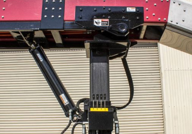
The Post
- 360° Rotation
- Ergonomic Controls
- Mounted Flush to Truck Bed (No Trip Hazard)
810-458-6445

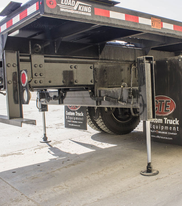
Vertical lift stabilizer with an adjustable swivel foot pad
| Lengths | 31' | 34' | 37' | 40' | 43' |
| Weights | 2977 lbs | 3041 lbs | 3105 lbs | 3169 lbs | 3233 lbs |
| Belt Speed | 75' / Minute | ||||
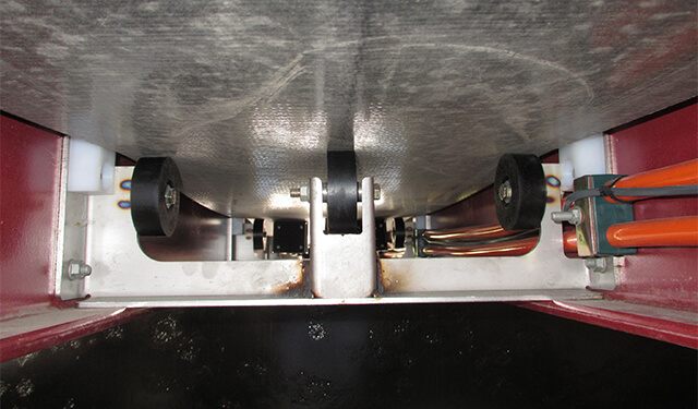
| Frame Structure | Fiberglass | ||||
| Shingle Delivery System | Hydraulic Belt | ||||
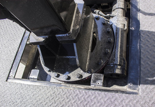
| POST/BASE | Hydraulic Telescoping Rotation 360° Continuous | ||||
| POST/BASE W/HYD HOSES | 1,070 lbs | ||||
| OUTRIGGER W/HYD HOSES(STABILIZERS) | 385 lbs | ||||
| WET LINE KIT (PTO, PUMP, TANK, PLATES, PARTS) | 200 lbs | ||||
| Truckbed Length | 20' | 22' | 24'6" | 27'6" | 30' |
| Conveyor Lengths | 31' | 34' | 37' | 40' | 43' |
| Cab to Axle (CA) / Cab to Turnion (CT) Recommended |
210 |
210 |
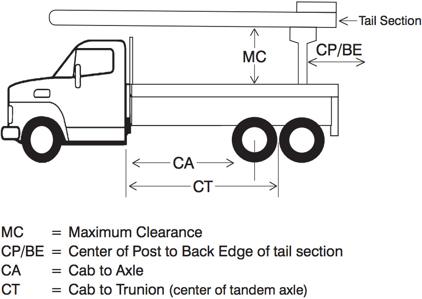
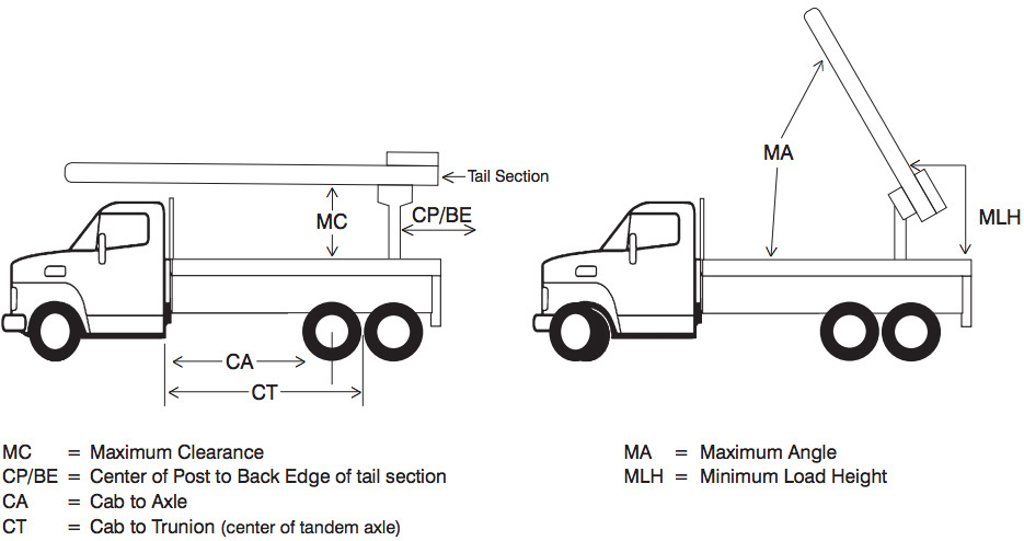
| Conveyor Length | 31' - 34' | 37' | 40' - 43' |
| Minimum Load Height (MLH) | 18" | 24" | 18" |
| Maximum Bed Clearance (MC) | 65.75 | 71.75 | 65.75 |
| Maximum Conveyor Angle (MA) | 61 1/2° | ||
| Center of Post to Back Edge of Tail Section (CP / BE) | 33 1/2 | ||
| Post Rotation | 360° Continuous | ||
